Fig/Tab
Rss
Email Alert
Adv Search
Home
About Journal
Editorial Board
Publishing Ethics
Subscriptions
Advertise
Contact Us
Download
中文
Introduction
Indexed-in
Journal Metrics
More options
Journal
DOI
ALL
CIESC Journal
Publication year from
To
All
1951
1952
1953
1954
1955
1956
1957
1958
1959
1960
1961
1962
1963
1964
1965
1966
1967
1968
1969
1970
1971
1972
1973
1974
1975
1976
1977
1978
1979
1980
1981
1982
1983
1984
1985
1986
1987
1988
1989
1990
1991
1992
1993
1994
1995
1996
1997
1998
1999
2000
2001
2002
2003
2004
2005
2006
2007
2008
2009
2010
2011
2012
2013
2014
2015
2016
2017
2018
2019
2020
2021
2022
2023
2024
2025
2026
All
2026
2025
2024
2023
2022
2021
2020
2019
2018
2017
2016
2015
2014
2013
2012
2011
2010
2009
2008
2007
2006
2005
2004
2003
2002
2001
2000
1999
1998
1997
1996
1995
1994
1993
1992
1991
1990
1989
1988
1987
1986
1985
1984
1983
1982
1981
1980
1979
1978
1977
1976
1975
1974
1973
1972
1971
1970
1969
1968
1967
1966
1965
1964
1963
1962
1961
1960
1959
1958
1957
1956
1955
1954
1953
1952
1951
Volume
Issue
Author
Affiliation
Search result
Journal
Loading ...
Publication year
Loading ...
Table 1 Composition of product gas from methanol-to-propylene device
[
3
]
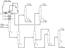
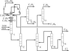
Fig.1
Schematic diagram of sequential separation technique (C
3
H
8
as absorbent)
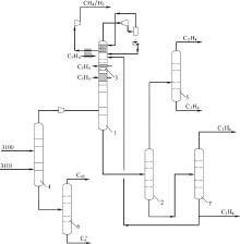
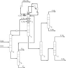
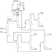
Fig.2
Schematic diagram of front-end depropanization separation technique (C
3
H
8
as absorbent)
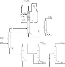
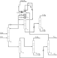
Fig.3
Schematic diagram of front-end deethanizer separation technique (C
3
H
8
as absorbent)
Table 2 Utility consume of sequential separation, front-end depropanizer and front-end deethanizer processes (C
3
H
8
as absorbent)
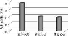
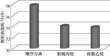
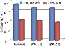
Fig.4
Comparison of standard fuel oil consumption in sequential separation, front-end depropanizer and front-end deethanizer processes (C
3
H
8
as absorbent)
Fig.5
Schematic diagram of sequential separation technique (C
4S
as absorbent)
Fig.6
Schematic diagram of front-end depropanizer separation technique (C
4S
as absorbent)
Fig.7
Schematic diagram of front-end deethanizer separation technique (C
4S
as absorbent)
Table 3 Utility consume of sequential separation, front-end depropanizer and front-end deethanizer processes (C
4S
as absorbent) (clear cutting rectification)
Fig.8
Comparison of standard fuel oil consumption in sequential separation, front-end depropanizer and front-end deethanizer processes(C
4S
as absorbent) (clear cutting rectification)
Fig.9
Standard fuel oil consumption of separation section using C
3
H
8
and C
4S
as absorbent individually
Fig.10
Schematic diagram of front-end deethanizer separation process (C
4S
as absorbent, non-clear cutting)
Table 4 Utility consume of front end de-deethanizer (C
4S
as absorbent)
Fig.11
Comparison of fuel oil consumption of front-deethanizer process (clear cutting and non-clear cutting)
Fig.12
Thermally coupled non-clear cutting process of front-end deethanizer separation technique (C
4S
as absorbent)
Table 5 Utility consume of thermally coupled front-end deethanizer separation technique (C
4S
as absorbent)
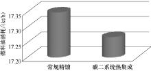
Fig.13
Comparison of standard fuel oil consumption in conventional and thermally coupled for non-clear cutting front-end deethanizer separation
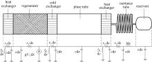
Fig.1
Main structural drawing of coaxial PTC
Fig.2
Acoustic impedance diagram of PTC
page
Page 1 of 2431
Total 48606 records
First page
Prev page
Next page
Last page